- 您现在的位置:买卖IC网 > Sheet目录625 > LC4HW-R6-DC24VS (Panasonic Electric Works)COUNTER DIGITAL 24VDC SCREW TERM
�� �
�
�LC4H-W�
�Setting� the� operation� mode� and� counter�
�Setting� procedure� 1)� Setting� the� output� mode� (output� 1,� 2)�
�Set� the� output� 1� and� output� 2� with� the� DIP� switches� on� the� side� of� the� counter.�
�The� minimum� input� signal� width� and� maximum� counting� speed� for� the� reset� are� set� at� the� same� time.�
�DIP� switches�
�1�
�2� Output� mode�
�4� Minimum� reset� input� signal� width�
�5� Maximum� counter� setting�
�6�
�7� Output� mode�
�Item�
�3� Output� 1�
�8� Output� 2�
�OFF� ON�
�Refer� to� table� 1�
�20ms� 1ms�
�30Hz� 5kHz�
�Refer� to� table� 2�
�Table� 1�
�DIP� swith� No.�
�1� 2� 3�
�ON� ON� ON�
�OFF� OFF� OFF�
�ON� OFF� OFF�
�OFF� ON� OFF�
�ON� ON� OFF�
�OFF� OFF� ON�
�ON� OFF� ON�
�OFF� ON� ON�
�Output� mode�
�(Output� 1)�
�(See� note� 1)�
�HOLD–B�
�HOLD–C�
�HOLD–D�
�SHOT–A�
�(See� note� 1)�
�(See� note� 1)�
�(See� note� 1)�
�DIP� switches� (see� note� 2)�
�Table� 2�
�DIP� swith� No.�
�Output� mode�
�1�
�2�
�3�
�4�
�5�
�6�
�7�
�8�
�6� 7�
�8�
�(Output� 2)�
�ON� ON�
�ON�
�HOLD–A�
�OFF�
�ON�
�OFF�
�OFF�
�OFF�
�ON�
�OFF�
�OFF�
�OFF�
�HOLD–B�
�HOLD–C�
�HOLD–D�
�ON� ON� OFF�
�SHOT–A�
�OFF�
�OFF�
�ON�
�SHOT–B�
�(Same� for� screw� terminal� type)�
�ON�
�OFF�
�OFF�
�ON�
�ON�
�ON�
�SHOT–C�
�SHOT–D�
�Notes:1)� The� counter� and� set� value� displays� will� display� DIP� Err.�
�Setting� procedure� 2)� Setting� the� set� value�
�Set� the� set� value� with� the� UP� keys� on� the� front� of� the� counter.�
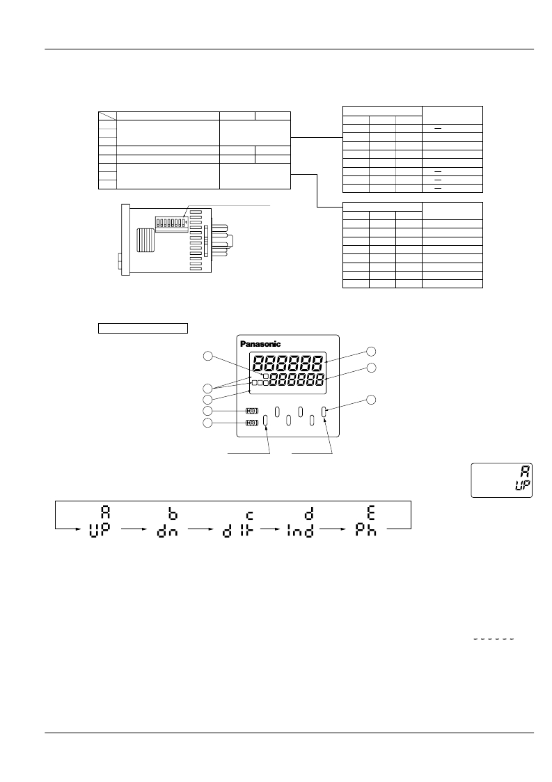
�Front� display� section�
�Notes:� 2)� Set� the� DIP� switches� before� installing� the� counter� on� the� panel.�
�Notes:� 3)� When� the� DIP� SW� setting� is� changed,� turn� off� the� power� once.�
�Notes:� 4)� The� DIP� switches� are� set� as� ON� before� shipping.�
�Q� Counter� display�
�W� Set� value� display�
�E� Controlled� output� indi-�
�cator�
�4�
�COUNTER�
�1�
�2�
�Y� UP� keys�
�[Changes� the� corresponding� digit� of�
�the� set� value� in� the� addition� direc-�
�tion� (upwards)]�
�R� Setting� 1/2� selection�
�display� (*Note)�
�T� Lock� indicator�
�*Note:�
�Pressing� the� [SET/LOCK]� key� switches�
�the� display� between� the� set� value� 1� and�
�2� displays.�
�Display� either� set� value� [1]� or� [2],� and�
�set� the� value.�
�Procedure� 3)� Setting� the� input� mode�
�3�
�5�
�7�
�8�
�OP.� 1�
�1� 2� 2�
�LOCK�
�RESET�
�SET/LOCK�
�Sixth� digit�
�LC4H-W�
�First� digit�
�6�
�U� RESET� switch�
�Resets� the� counting� value� and� the�
�output�
�I� SET/LOCK� switch�
�Used� to� select� between� the� Setting�
�1� display� and� Setting� 2� display,� to�
�set� and� confirm� the� input� mode,� and�
�to� lock� the� keys� (UP� and� RESET�
�keys� not� responsive� to� touch).�
�Set� the� input� mode� using� the� key� and� switch� in� the� front� display� section� on� the� counter� front.�
�(1)� Hold� down� the� SET/LOCK� key� and� press� the� UP� key� for� the� first� digit.� The� setting� mode� is� accessed.�
�(2)� Now� release� the� SET/LOCK� key.�
�(3)� Press� the� UP� key� for� the� first� digit� and� the� input� position� changes� counterclockwise.�
�Example)�
�Input� mode� displayed�
�(UP:� addition� mode)�
�Addition�
�subtraction�
�Directive�
�Independent�
�Phase� difference�
�(4)� Press� the� RESET� key� and� the� input� mode� being� displayed� is� set.� The� display� then� goes� back� to� normal.�
�?� Checking� the� input� mode�
�Hold� down� the� SET/LOCK� key� and� press� the� UP� key�
�for� the� second� digit.� The� input� mode� is� displayed� for�
�about� 2� seconds� and� then� the� display� goes� back� to�
�normal.� (During� these� 2� seconds,� all� operations�
�other� than� the� display� are� being� performed.)�
�?� Locking� the� keys�
�Hold� down� the� SET/LOCK� key� and� press� the� UP� key�
�for� the� sixth� digit.� The� keys� will� lock.� This� means� that�
�the� UP� and� RESET� keys� do� not� respond� to� touch.� To�
�unlock� the� keys,hold� down� the� SET/LOCK� key� and�
�press� the� UP� key� for� the� sixth� digit� again.�
�*� The� input� mode,� maximum� counting� speed� and� minimum�
�reset� signal� width� cannot� be� preset� independently� for� Setting�
�1� and� Setting� 2.�
�?� Selecting� the� Setting� 1� or� Setting� 2� dis-�
�?� Changing� the� setting�
�1.� While� the� counter� is� working,� the� UP� key� can�
�be� used� to� change� the� setting.� Keep� the� follow-�
�ing� points� in� mind,� however.�
�1)� Suppose� that� a� preset� count-up� value� is� smaller�
�than� the� displayed� count� value.� The� counter� counts�
�up� to� the� full� scale� mark� (999999),� goes� back� to� "0",�
�and� counts� up� again� to� the� preset� number.� When� the�
�preset� count-up� value� is� larger� than� the� displayed�
�count� value,� the� counter� counts� up� to� the� preset�
�value.�
�2)� Suppose� that� the� counter� is� preset� to� count� down.�
�Whether� a� preset� count-down� value� is� smaller� or�
�larger� than� the� count� value,� the� counter� counts� down�
�to� "0".�
�2.� When� the� preset� value� is� "0",� the� counter� does�
�not� start� in� the� count-up� mode.� It� starts� counting�
�up� when� the� count� value� comes� to� "0"� again.�
�1)� Up-count� input�
�The� counter� counts� up� to� the� full� scale� mark�
�(999999),� goes� back� to� "0"� and� starts� counting� up�
�again.�
�2)� Down-count� input�
�The� counter� counts� down� to� the� full� scale� mark�
�(–99999)� and� the� display� reads� .� The�
�count� value� does� not� become� "0"� and� so� the� counter�
�does� not� count� up.�
�3)� Direction� input,� individual� input,� and� phase� input�
�The� preset� value� is� counted� up� or� down� to� any� num-�
�ber� other� than� "0"� once.� When� it� comes� to� "0"� again,�
�the� counter� starts� counting� up.�
�play�
�Press� the� SET/LOCK� key� and� the� display� changes�
�between� Setting� 1� and� Setting� 2.� (This� operation�
�does� not� affect� overall� operation.)�
�All� Rights� Reserved� ?� C� OPYRIGHT� Matsushita� Electric� Works,� Ltd.�
�发布紧急采购,3分钟左右您将得到回复。
相关PDF资料
LCS-10
LIQUID LEVEL CONTROL
LD4006P0
COUNTER 6 DIGIT DUAL 4.0" RED
LD412460
DIODE MOD ISO DUAL 2400V 600A
LIRT220A
CONTROL RELAY CURRENT 220VAC
LNXC2000
COUNTER DUAL PRESET 115VAC
LP-56-850
XFRMR 115/230V 28V 1.7A 48VA PCB
LS412460
DIODE MOD ISO SGL 2400V 600A
M4L-3-10
XFRMR 115V 8.7A 1000VA
相关代理商/技术参数
LC4HWT6AC24V
制造商:OMRON 功能描述:*
LC4-MFD
制造商:Bosch Sensortec 功能描述:Metal Fire Dome for LC4 Series Loudspeakers
LC-4-S Black
制造商:Mac8 功能描述:
LC-4-S Blue
制造商:Mac8 功能描述:
LC-4-S Yellow
制造商:Mac8 功能描述:
LC4-UC06E
制造商:Bosch Sensortec 功能描述:Premium ceiling wide angle loudspeaker, 6 watt, EVAC compliant
LC-5
功能描述:打印机 LS3E, Component Label, Adhesive Vinyl Cl RoHS:否 制造商:Seiko Instruments 产品:Printer 电源电压: 每行点数:9 x 320 打印速度:52.5 cps, 80 cps 纸张宽度:112 mm
LC-5.0
功能描述:LED 光导管 Light Pipe Flex 4mm Round Lens RoHS:否 制造商:Bivar 产品:Light Pipes 颜色:Clear LED 大小: 主体形状:Cylindrical 主体长度:0.125 in 材料:Polycarbonate